Milliwatt AM Transmitter For 13.560
By Tha DoodA small transmitter intended for use in the 13 megahertz ISM (Industrial, Science and Medical) band under Part-15, which allows several milliwatts of power output. That sounds small, but the signal has been reported to reach a few miles locally, and hundreds of miles when shortwave propagation is good.
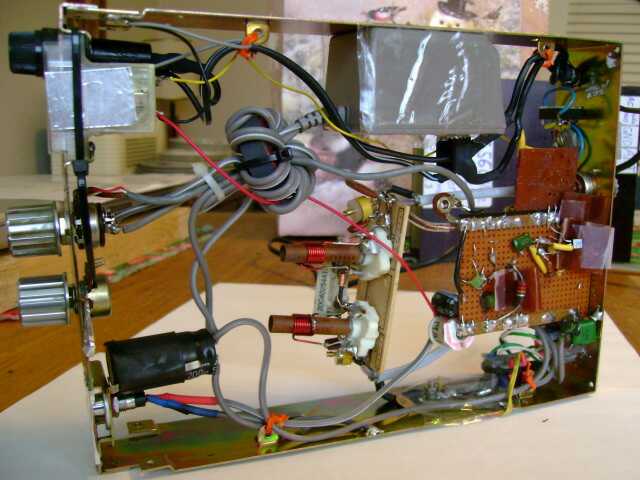
Top side of the transmitter, built into a mobile CB case
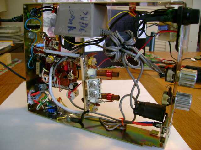
Bottom of the transmitter, open construction allows easy reach for modification and repair
Nothing in the circuit gets warm, Tha Dood says: "Maybe that wallwart gets a little
luke-warm. I haven't noticed heat from that 2N3904 final either."
He also says, grounding the 13.560MHz crystal seems
to take away any incidental phase modulation. "On FM, it's the
quietest AM TX that I've tested, thus far, commercial, or consumer.
On the TS-2000X on FM mode, I have to crank the volume all the way
just to notice anything."
"Only one problem, is on audio bandwidth, it's not
frequency limited. Thus, why I used the audio output of a
Realistic AM only 1975 radio. Audio bandwidth is limited with that.
Very simple, but effective. "
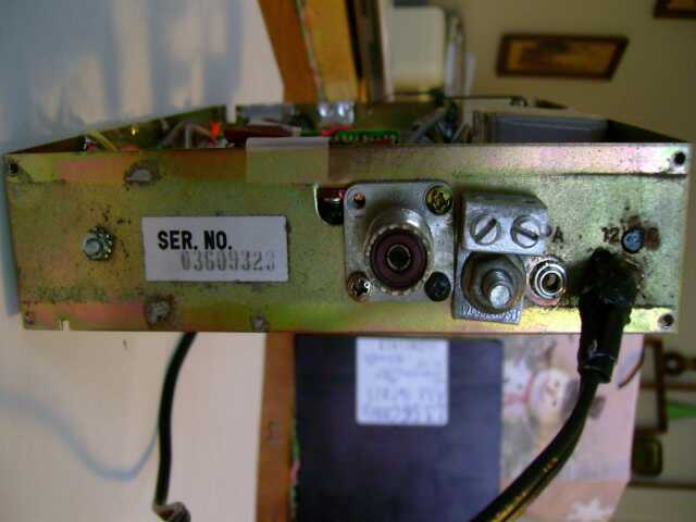
Back of transmitter, with antenna socket, grounding block, audio input and AC power cord
"What's the RF output of this TX? I calculated it from 500uW to MAX out at 18mW. At MAX RF, it
doesn't MOD well at all, so that 200mA wallwart certainly limits things. If you put this into an HF
power / VSWR meter, on it's lowest scale, the meter pointer may move only the width of the
pointer itself. How's that for low? I have to use my MFJ antenna analyser to match an antenna to it.
Consider this, at even 2mW and a perfectly matched 13.560MHz dipole, this TX will cover miles
locally, and via Part #15."
"With that CB meter in it, when it indicated a "10" on that scale, that's about a 2mW carrier."
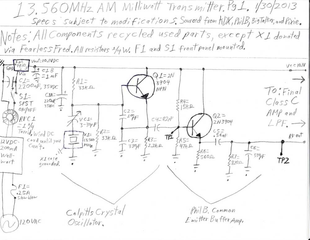
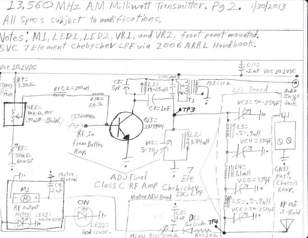
Schematic: Power, oscillator, driver and final amp, filtering
| R1 | 33k | C6 | 330pf |
| R2 | 33k | C7 | 1nf |
| R3 | 2.2k | C8 | 5pf |
| R4 | 15k | C8-2, C9 | 1uf |
| R5 | 47k | VC1 | 3-30 pf trimmer |
| R6 | 560 ohms | VC2 | 5-70pf |
| R7 | 820 ohms | VC3, VC6 | 50-200pf |
| R8 | 50k trimpot | VC4, VC5 | 330 pf variable |
| R9 | 3.3k | Q1, Q2, Q3 | 2N3904 NPN |
| VR1 | 10k trimpot (pwr. adjust) | X1 | 13.560 Mhz. Crystal |
| R10 | 1K | L1 | 19-25uh |
| R11 | 1k | L2 | 3.44uh |
| R12 | 50k trimpot | L3, L5 | .5-.9uh |
| L4 | 1.1uh | ||
| C1 | 2200uf, 35 volt | Regulator | LM7810 |
| C1A | 220uf, 35 volt | M1 | Meter 1 ma assumed |
| C2 | 100pf | F1 | 250ma slo-blo |
| C3 | 330pf | D1 | Germanium diode |
| C4 | 82pf | LED1, 2 | White, red 12 volt indicators |
| C5 | .56uf | RFC2 | 100uh |
| C11 | .1uf | RFC3 | 19uh |
Extras: 12 volt 200 milliamp DC power supply cube, Ferrite toroid (RFC1), modulation transformer (T1): 17:42 ohms, 1/8-inch audio jack (3.5mm), SO-239 coaxial antenna jack

"On the 'scope, the output of this TX was very clean. Anyway, good luck building!"