
Transmitter audio setup is pretty much the same as would be used on an FM station, with limiting, 75 microsecond pre-emphasis and an audio cutoff at 15 khz. It has none of the special processing that's typically used with AM stereo, such as matrix processing or single channel limiting; instead I reduce the L-R drive level after the processing, relative to L+R.
For the following demos it's probably best to use a good quality speakers, or at least a system your ears are familiar with, to judge the relative sound quality of what you're about to hear. The audio was recorded with a Zoom H2 microphone to 44/16 wav with level control off, connected directly to the tuner's output.
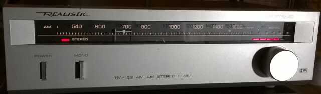
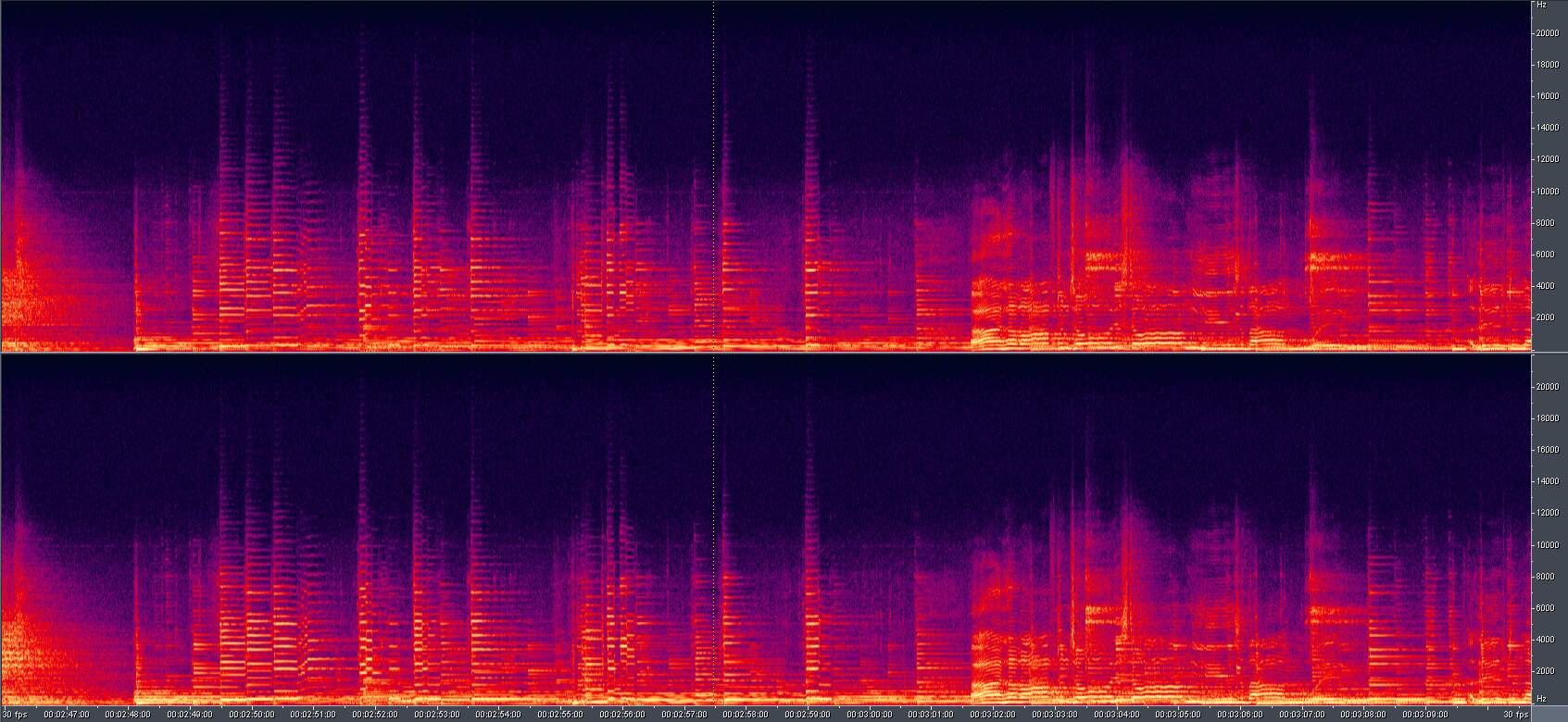
Below is a spectrum display from this vintage 1986 Realistic tuner, playing a short song segment with guitar and vocals. The response gets close to 10 khz, and is pretty much gone by 12 khz, in a smooth roll-off, so it doesn't sound so bad. As you listen to the files you may note that the Realistic favors the midrange, which might be due to a combination of the transmitter's pre-emphasis with the receiver's high frequency roll-off. In the mid-1980s, pre-emphasis wasn't standardized, so receivers didn't have to be designed for treble-boosted audio.
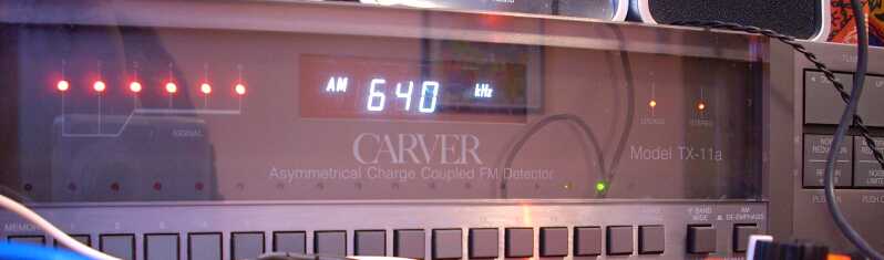
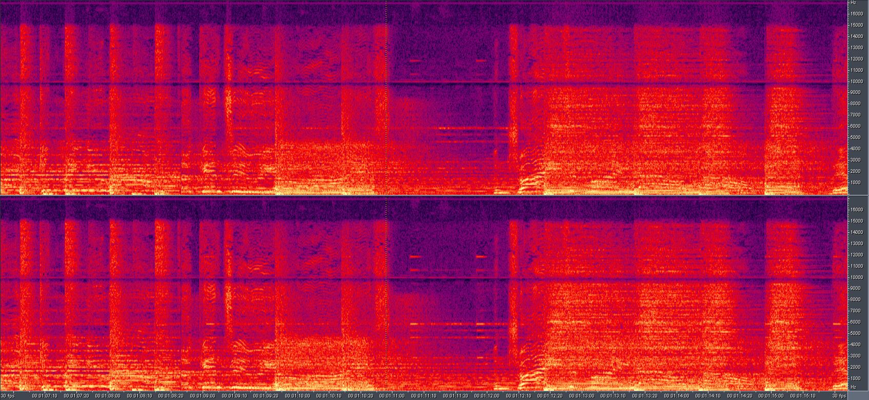
The spectrum display below shows about 9 seconds of Yes' song, Changes. It's a really 'filled up' spectrum on this highly produced track that has lots of echo and harmonics. It shows audio response extending to 15000 hz, and an interesting thing to see the dark purple line which is the Carver's notch filter 'missing' the 10 khz mark by being a few hundred hertz low! Praise be to Carver for being able to get a notch that narrow.. Right above the notch is the line for the 10 khz tone caused by heterodyne from adjacent station carriers. I'd estimate my signal level to be at about 100 millivolts at the Carver's loop.
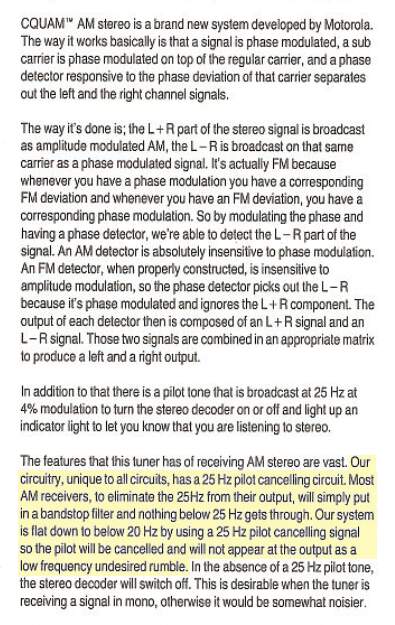
A section from the Carver tuner's manual about C-QUAM
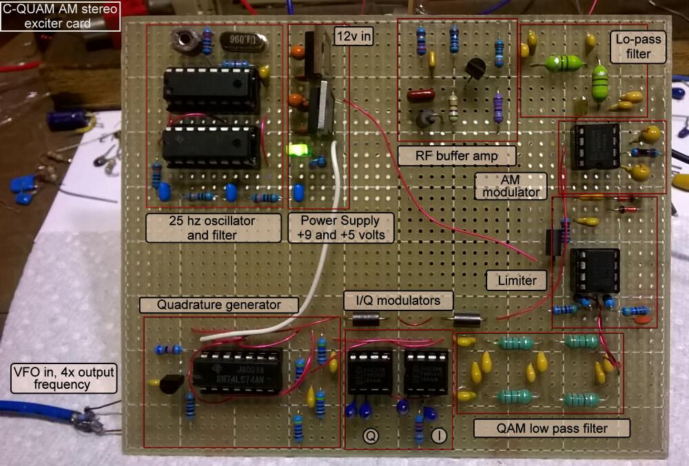

25 hz pilot circuit |
My AM stereo modulator card is based on Alfredo's design. It strips out all of his audio circuits and feeds the 'I' and 'Q' modulators directly from a computer's left and right outputs, through a plugin program called Mid-Side Mangler, which makes left computer output 'mid' and the right output act as 'side'. Mid feeds directly into the 'I' input on the modulator, and Side goes to the 'Q' input. I plan to change to a traditional dual op-amp matrix though, to save computer power from running Mid-Side Mangler.
My addition to Alfredo's circuit is the crystal controlled pilot oscillator. The 25 hertz stereo pilot frequency is generated by dividing a 4,096,000 hz crystal by 163,840 for a 25 hz output that's fiendishly stable.. :) That's done using a CD4060 ripple counter IC, feeding a 4017 decade counter, then RC filtering it, very simple, and the lowest parts count crystal pilot generator I've seen. Additionally, the Q12 output of the 4060 is 1 khz, which could later be used as a PLL reference, making a range of broadcast frequencies available, and the pilot, all from a single crystal. Using a balanced modulator for phase modulation is not a new idea, Armstrong patented it in 1933. Quadrature modulation seems to be a logical next step. See: https://en.wikipedia.org/wiki/Armstrong_phase_modulator |

This is beta setup for the stereo board, and the dinner plate is there to hold and insulate the circuit from touching anything. The low level RF output from the stereo board (about 1 volt p-p) goes through a twisted pair of clip leads to the RF power adjust control on the LPB transmitter's circuit board and is simply amplified, to 5 watts. This little room is literally under ground, so we really are Underground Radio. The power panel is located above the coupler in the upper right, out of the picture. I wanted to be as close to where the line comes in from the street as possible, with the hope that more signal would get out into the grid.
I use a different method of coupling than the usual one, which is connecting the coupler to several phases directly, and having AC power inside of the coupler. Mine doesn't require access to the inside of the breaker box, just a short section of the line coming into it from the street. Around about 5 inches of the line is wrapped a tube of sheet copper. At the top and bottom of it 12 gauge wires are soldered, and those go to the outputs on the coupler, the neutral and a hot. Ferrite blocks (large donut cores) are placed around the copper tube and line, making a transformer, with the 1-turn copper tube primary fed by the coupler, and the secondary being the power line itself, feeding both AC phases and neutral in parallel. I found that feeding all at once allows balanced current through the transformer, for low hum levels on the signal.
The copper tube is the feedpoint, and if you imagine the split where a dipole would be fed, it's like that, with the hot side being the line to the street, and the ground side or cold end being the power line grounds, which are two ground rods outside, and a cold water pipe ground inside as well.
My hope is that stations will innovate around the idea of transformer coupling and try it themselves, because it's safer than a direct connection to the AC main, and less intrusive if you rent, which ought to get more stations trying carrier current.
Here's a video that talks about how the C-QUAM system works: https://www.youtube.com/watch?v=Tg3X6dVAYBs
Page by Boomer The Dog ![]()